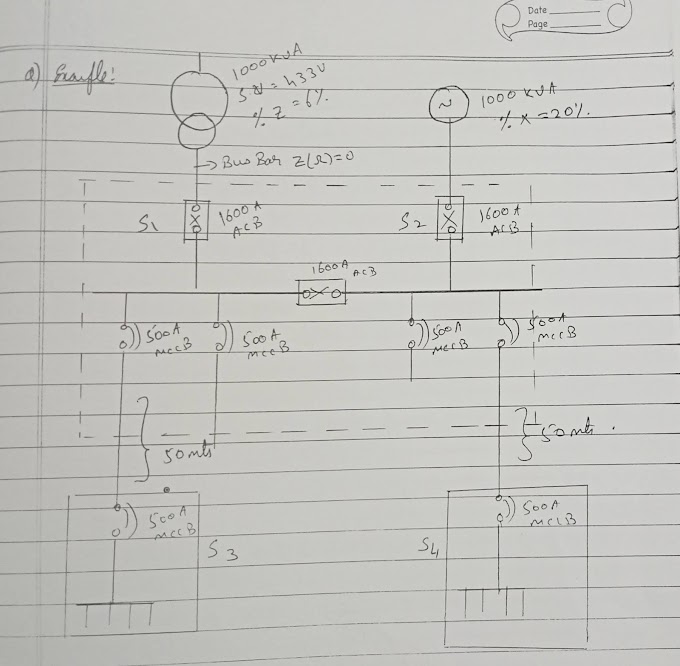
Transformer :
Transformer is a device
1) Transfer electrical power from one electrical circuit to another electrical circuits.
2) It's working without changing the frequency.
3) Work through on electric induction.
4) Can't step up (or) step down the level of DC voltage (or) DC current.
5) Can step up (or) step down the level of AC voltage (or) AC current.
Parts of Transformer :-
1) Oil filter value
2) Conservation
3) Buchholz relay
4) Oil filter value
5) Pressure - relief vent
6) High voltage bushing
7) Low voltage bushing
8) Suspension lug
9) B.C.T terminal
10) Tank
11) De - energized tap changer
12) Tap changer handle
13) Fastened for core and coil
14) lefting hook for cook and oil
15) End frame
16) Coil pressure bolt
17) Oil drain valve
18) Jacking bass
19) Stopper
20) Foundation bolt
21) Coil
22) Coil pressure plate
23) Core
24) Terminal bos for protection device
25) Relay plate
26) Radiator
27) Manhole
28) Dial type oil level Group
Types of Transformer :-
Transformers can be categorised in different ways depending upon their purpose, uses, construction etc..
There are two basic types of transformer :
1) Single phase transformer
2) Three phase transformer
Below are the more types of Transformer derived via different function and operation etc..
Transformer cores :
* Shelt type transformer
* Berry type transformer
Types of cooling in transformer :
* Self air cooled (or) dry type transformer
* Air blast cooled deny type transformer
* Oil immersed, self cooled (OISC)
* Oil Natural, Air Natural (ONAN)
* Oil immersed, water cooled (OW)
* Oil forced, Air forced cooled (OFAC)
* Forced oil, water cooled (FOWC)
Types of Instruments :
* Current transformer
* Potential transformer
* Constant current transformer
* Rotating Core transformer (or) Inductor regulator.
Operating & Working principal of Transformer:-
Transformer is static device ( and doesn't contain on rotating parts, hence no friction losses). Which converts electrical power from one circuit to another without changing it frequency. It step up or down the level of AC voltage and current.
Transformer works :
Transformer works on the principle of mutual Induction of two coil (or) Faraday laws of electromagnetic induction. When current is the primary coil is changed the flux linked to the secondary coil also change consequently an EMF is induced in the secondary coil due to Faraday laws of electromagnetic induction.
The transformer is based on two principal. First, that as electric current can produce a magnetic field and second, that's a changing magnetic field a coil of wire induces a voltage across the ends of the coils ( electrons magnetic Induction) changing the current in the primary coil change the magnetic flux that is developed. The changing magnetic flux induces a voltage in the secondary coil.
A simple transformer has a self iron (or) silicon steel core and winding placed on it (iron core) . Both the core and the winding are insulated from each other. The winding connected to main supply is called primary winding and the winding connected to the load current is called secondary winding.
As explained earlier, EMF is induced only by variation of magnitude of the flux.
When the primary winding is connected to AC main supply, a current flow through it. Since the winding links with the core, current flowing through the winding will produce in alternating flux in the core. EMF is induced bin the secondary coil. Since the alternating flux links the two winding. The frequency of the induced E.M.F. is the same as that flux or the supply voltage.
By so doing (variation of flux) energy is transferred from the primary coil to the secondary coil by means of electromagnetic induction without the change the frequency of the voltage supply to the transformer. During the process, a self induced EMF is produced in the primary coil which opposes the applied voltage. The self induced EMF is known as Back EMF.
• Types of connection in transformer :
Delta - Delta (∆-∆)
Delta - Star (∆-¥)
Star - Star (¥-¥)
Formula :
(KW)
1- Φ P= V×I∞ cosΦ
3 - Φ. P= √3×V×I∞ cosΦ×Π
(KVA)
1- Φ P= V×I
3 - Φ. P= √3×V×I
(KVAR)
1- Φ P= V×I sin Φ
3 - Φ. P= √3×V×I sin Φ
• Standard voltage of transformer :
220/230/240V -- 1- Φ
415/430/440/480 -- 3 - Φ
800 V
3.3 KV
6.6 KV
11 KV
33 KV
66 KV
132 KV
220 KV / 266 KV
440 KV / 400/ 380/ 366 KV
765 KV / 750 KV
500 KV
666 KV
1050 KV .
• Rectifier :
AC → DC
• Invertor :
DC → AC
• Filters :
Filters are use to reduce the harmonics and
derivative the wave forms.
• Motor :
1 to 5 kw → 230 v
5 to 250 kw → 415 v
250 to 500 kw → 3.3 kv
500 to 750 kw → 6.6 kv
Above 750 kw → 11 kv.
• Thumb rules for construction :
Kw × 5.32 = Amps @ P.F. : 0.8 (1 - Φ)
Or
Kw × 6 = Amps @ P.F. : 0.8 (1 - Φ)
Or
Kw × 8 = Amps @ P.F. : 0.6 (1 - Φ)
Kw × 1.74 = Amps @ P.F. : 0.8 (3 - Φ)
Or
Kw × 1.9 = Amps @ P.F. : 0.8 (3 - Φ)
KVA × 1.4 = Amps (3 - Φ)
H.P × 1.5 = Amps (3 - Φ)
H.P × 0.746 = kw
KVAR × 2.0 = Amps
Or
KVAR × 1.6 × 1.25 = Amps
• Power Factor (P.F) :
If the P.F increasing current is decreasing hence the cost (or) bill is less.
• Resistive load :
Voltage and current are in phase.
• Inductive load :
Voltage lead and current lag.
• Capacitive load :
Current lead and Voltage lag.


0 Comments